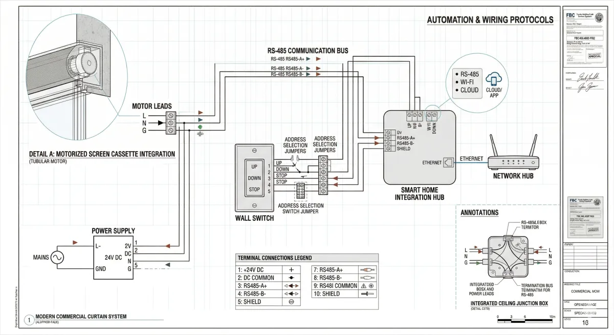
Motorized Screen Automation Protocols: Smart Home Integration, Control Systems, and Wiring Standards
Control System Specification Begins With Protocol Selection, Not Product Selection
The motorized screen motor arrives on site as a mechanical device with a defined wiring interface. What determines whether that device integrates correctly into the project's control environment is not the motor itself, but the decisions made weeks earlier during the specification phase: which control protocol the motor supports, how the wiring topology is designed, where the control panel is located, how the smart home or BAS platform interfaces with the motor's native signal, and what commissioning procedure confirms that every integration point is functional before the owner occupies the building.
Engineers who make these decisions after the motor is on-site, by interpreting field conditions and improvising wiring solutions, produce integrations that function inconsistently, fail during commissioning, and generate service calls within the first year of occupancy. The control system specification must be developed in parallel with the motor specification and must be documented with the same rigor applied to any other low-voltage system in the construction documents.
This guide provides engineers with the complete technical framework for motorized screen automation specification: from protocol selection through wiring standards compliance, control topology design, smart home bridge integration, and commissioning verification. The technical library at Next Gen Screens provides product-specific control system documentation to support this process.
Control Protocol Architecture: Selecting the Right Protocol for the Project Scope
The fundamental specification decision for any motorized screen control system is the protocol that will carry commands from the control interface to the motor. This selection determines everything downstream: the wiring topology, the interface hardware, the smart home compatibility, and the commissioning procedure. Protocol selection must be made during the design phase, not the procurement phase.
Hardwired 3-Wire and 5-Wire Line-Voltage Control
The simplest and most universally compatible control configuration for AC tubular motors is the 3-wire hardwired system: a common (neutral) conductor, an UP conductor, and a DOWN conductor. A dedicated 120V AC power source at the motor feeds the common conductor permanently. Applying 120V to the UP conductor through a wall switch, relay, or timer commands retraction; applying 120V to the DOWN conductor commands deployment. The motor's internal end-limit switches terminate movement at the fully retracted and fully deployed positions without external signal.
The 5-wire variation adds a dedicated limit signal conductor and an auxiliary output conductor. The auxiliary output provides a voltage-free contact signal that confirms the motor has reached its travel limit, enabling integration with relay logic controllers, panel-level monitoring systems, and commercial BAS platforms that require position confirmation before proceeding with dependent automation sequences.
Wiring standard compliance: All line-voltage motor control wiring must comply with NEC 2023 Article 430 (Motors) and Article 300 (Wiring Methods). In exterior and wet locations, conductors must be rated for wet location use (THWN-2 minimum), installed in liquidtight flexible metallic conduit (LFMC) or Schedule 80 PVC conduit. All conduit runs must be sealed at points of entry into conditioned spaces to prevent moisture migration.
Application scope: 3-wire and 5-wire hardwired control is appropriate for single-motor or small multi-motor installations where individual wall switch control of each screen is the specified operating mode, and where smart home or BAS integration is not required or is accomplished through a bridge device external to the motor wiring.
RS-485 Serial Bus: Somfy SDN and Compatible Protocols
RS-485 is the physical layer standard for the most widely deployed wired network protocol in motorized screen and roller shade applications. Somfy's Digital Network (SDN) protocol operates over a twisted-pair RS-485 bus, enabling individual motor addressing, bidirectional communication, and position reporting on a single two-conductor cable run that can serve up to 32 motors before requiring a repeater.
SDN network architecture:
The SDN bus is a multi-drop topology: a single twisted-pair cable runs from the SDN controller to each motor in sequence, with the last motor on the run terminated with a 120-ohm resistor. Each motor on the bus is assigned a unique node address (1 through 255) during commissioning. The SDN controller sends addressed commands to individual motors or to group addresses that trigger simultaneous deployment of multiple motors on a single command.
Key SDN specifications for engineer documentation:
Bus cable: 2-conductor twisted pair, minimum 22 AWG, shielded preferred for runs exceeding 30 meters or in environments with high electrical noise
Maximum bus length: 1,200 meters (approximately 3,900 feet) without a repeater; with an SDN repeater, bus length can be extended to 2,400 meters
Maximum motors per segment: 32 before requiring a repeater or hub
Termination: 120-ohm resistor at the terminal motor on each bus segment
Controller interface: SDN controllers typically interface with building management systems or smart home platforms through RS-232, USB, or Ethernet ports; the specific interface must be confirmed against the BAS or smart home platform's available inputs
Wiring standard compliance for RS-485 low-voltage control wiring: RS-485 bus wiring is Class 2 low-voltage wiring under NEC 2023 Article 725. Class 2 wiring is permitted to be installed without conduit in concealed locations within walls and ceilings, subject to the separation and installation requirements of Article 725. In exterior or wet locations, the bus cable must be rated for the environment; shielded outdoor-rated twisted pair is required for exposed exterior cable runs.
Somfy RTS: Radio Technology Somfy
Somfy's RTS (Radio Technology Somfy) protocol is a unidirectional 433.42 MHz radio frequency protocol that enables wireless motor control without any wiring connection between the controller and the motor. Each RTS motor contains a factory-installed radio receiver that responds to RTS-protocol commands from registered transmitters (wall-mounted or handheld remotes) or from RTS-compatible smart home bridge devices.
RTS limitations that engineers must document:
RTS is a one-way protocol: the controller can send commands to the motor, but the motor cannot report its position or operational status back to the controller. This means that a BAS or smart home platform integrating with RTS motors through a bridge device cannot confirm whether a commanded deployment or retraction was completed, cannot detect a motor fault, and cannot read current screen position. For projects where position feedback, fault alerting, or logged operational data are required, RTS is not the appropriate protocol and SDN or a network protocol should be specified.
Bridge device integration for smart home platforms: RTS motors can be integrated with major smart home platforms (Amazon Alexa, Google Home, Apple HomeKit, Samsung SmartThings) through bridge devices such as the Bond Bridge Pro. The bridge device receives IP-based commands from the smart home platform and translates them into RTS radio signals that the motor receives. The engineer must document the bridge device model, its network connection requirements (Ethernet or Wi-Fi), its power supply specification, and its mounting location in the low-voltage systems drawing package.
KNX Building Automation Integration
For commercial projects where motorized screens are integrated into a comprehensive building automation system, KNX (EN 50090/ISO/IEC 14543) is the preferred integration standard. KNX is the only open, manufacturer-independent standard for building automation, supported by over 500 manufacturers and used in commercial projects across more than 190 countries.
KNX Physical Layer and Topology for Motorized Screens
KNX supports four physical transmission media: twisted-pair (TP), powerline (PL), radio frequency (RF), and IP. For motorized screen applications, KNX TP (twisted-pair) is the standard physical layer. KNX TP uses a dedicated 2-conductor YJCBY bus cable (or equivalent national standard), typically 0.8 mm diameter conductors, powered by a 29V DC KNX power supply that feeds both the bus communication signal and the device operating voltage for the bus-connected actuators.
KNX topology for motorized screen integration:
KNX TP is organized in a line-area-backbone hierarchy. Each KNX line supports up to 64 devices (with a line coupler, up to 256 devices per line). For motorized screen projects, the typical KNX integration topology is:
One KNX blind/shutter actuator module per zone (typically a DIN-rail mounted module with 2 to 8 actuator channels, each channel independently controlling one motor)
Each actuator channel wired to the motor using 3-wire or 5-wire line-voltage wiring per the motor manufacturer's specification
The KNX actuator module connected to the KNX TP bus for command reception and position reporting
ETS programming requirements: KNX devices are programmed using ETS (Engineering Tool Software), the official KNX programming application. Each blind/shutter actuator must be programmed with the correct group addresses for UP, DOWN, STOP, and position setpoint commands, and the group addresses must match the addressing structure defined by the project's KNX integrator. Engineers specifying KNX-integrated motorized screens must confirm that the KNX integrator has been engaged and that the group address structure for the screen system has been assigned before the equipment is ordered.
Specifying Motorized Screen Control Systems for Your Next Project?
One Track's engineering documentation includes protocol-specific wiring diagrams, SDN network topology drawings, and smart home integration specifications formatted for low-voltage system submittals. Access One Track's engineering resources at onetrackscreens.com
Residential Smart Home Integration: Z-Wave, Zigbee, and Wi-Fi Bridge Systems
For residential projects where motorized screens are integrated with a smart home platform rather than a commercial BAS, the control protocol selection is driven by the smart home platform already specified for the project and by the motor manufacturer's compatible integration pathway.
Z-Wave Integration (ITU-T G.9959)
Z-Wave operates at 908.42 MHz in North America on a mesh network topology where each powered Z-Wave device acts as a repeater, extending the network's effective range. Z-Wave is supported by over 3,000 certified devices and is natively compatible with major smart home hubs including SmartThings, Hubitat, Home Assistant, and Control4.
Z-Wave integration requirements for motorized screens:
Z-Wave does not interface directly with the motor's wiring. Integration requires a Z-Wave-compatible in-wall or DIN-rail motor controller module that sits between the Z-Wave network and the motor's 3-wire line-voltage inputs. The controller module receives Z-Wave commands from the hub, translates them into the appropriate 120V AC switching sequence for the motor's UP and DOWN conductors, and reports motor position back to the Z-Wave hub if the motor and controller support position feedback.
Engineers specifying Z-Wave integration must document: the Z-Wave hub model and its network address, the Z-Wave motor controller module model and its enclosure/mounting location, the wiring diagram showing the controller module's connection to the motor's 3-wire inputs, and the Z-Wave network pairing procedure for commissioning documentation.
NEC 2023 Article 725 compliance for Z-Wave wiring: Z-Wave controller modules connected to line-voltage motor wiring must be listed for the application and installed in compliance with both Article 725 (for the Z-Wave signal wiring) and Article 430 (for the motor branch circuit). The controller module enclosure must be rated for the installation environment; outdoor-rated enclosures are required where the module is installed in non-conditioned exterior locations.
Zigbee Integration (IEEE 802.15.4)
Zigbee operates at 2.4 GHz on a mesh network using the IEEE 802.15.4 physical and MAC layer standard. Zigbee is the native protocol for major smart home ecosystems including Amazon Alexa (with Zigbee hub), Philips Hue, IKEA TRÅDFRI, and Samsung SmartThings.
Key Zigbee specification considerations for motorized screen integration:
The 2.4 GHz operating frequency is shared with 802.11b/g/n Wi-Fi networks, Bluetooth, and microwave ovens. In environments with dense Wi-Fi deployments (commercial offices, multi-family residential), Zigbee network performance can be affected by co-channel interference. Engineers specifying Zigbee for commercial or multi-unit residential motorized screen projects should conduct a Wi-Fi channel analysis to confirm that the project's Wi-Fi deployment has not saturated the 2.4 GHz spectrum channels that Zigbee uses (channels 11, 15, 20, and 25 of the Zigbee channel plan correspond to the gaps between 802.11 channels 1, 6, and 11).
For residential single-family projects where Wi-Fi interference is limited, Zigbee is a reliable choice with a broad ecosystem of compatible motor controllers and hub platforms.
Wi-Fi Direct Bridge Integration
Wi-Fi direct bridge integration eliminates the need for a separate Z-Wave or Zigbee hub by connecting the motorized screen system directly to the building's 2.4 GHz Wi-Fi network through a dedicated bridge device. The most widely deployed bridge device for residential motorized screen integration in North America is the Bond Bridge Pro, which supports Somfy RTS, RF Zigbee, and several other motor protocols and exposes the integrated motors as devices on the Amazon Alexa, Google Home, Apple HomeKit, and IFTTT platforms.
Wi-Fi bridge specification requirements:
Network connection: Ethernet (recommended for reliability) or 2.4 GHz Wi-Fi
Power supply: 5V DC via USB-C; requires a 120V AC outlet within the cable run distance of the bridge device's mounting location
Motor compatibility: confirm the specific bridge device model supports the motor's native protocol (RTS, Zigbee, or other) before specifying
Smart home platform compatibility: confirm the bridge device's cloud integration supports the specific smart home platform version deployed on the project; cloud API compatibility can change with platform software updates
A critical limitation for engineers to document: Wi-Fi bridge devices that rely on cloud API integration are dependent on third-party cloud service availability. If the cloud service experiences an outage, remote control through the smart home platform is unavailable. Local control through the bridge device's own app or through directly paired wall switches is typically maintained during cloud outages, but the engineer's documentation should note this dependency and confirm with the owner whether a cloud-dependent integration is acceptable for the project's operational requirements.
Astronomical Time Clock Integration and Scene Programming
For projects where motorized screens are specified to deploy and retract automatically based on solar position, the control system must include an astronomical time clock function that calculates sunrise, sunset, and solar angle positions for the building's geographic coordinates without requiring daily manual schedule adjustments.
Astronomical Time Clock Specification
An astronomical time clock calculates the sun's altitude and azimuth for a specified latitude, longitude, and UTC offset on any given date, enabling schedule-based deployment commands that automatically adjust for seasonal variation in sunrise and sunset times without reprogramming. Most modern smart home hubs (Control4, Lutron, Crestron, Savant, and Homeworks) include native astronomical time clock functions. Standalone astronomical time clocks (Astronomic Timer, Intermatic astronomical timers) are available for simpler systems where a full smart home hub is not deployed.
Latitude/longitude input requirement: The astronomical time clock must be programmed with the project's latitude and longitude to within 0.1 degree accuracy. For Florida projects, latitude ranges from approximately 24.5°N (Florida Keys) to 31.0°N (Pensacola). A default latitude setting for "Florida" is not sufficient; each project requires site-specific coordinate input.
Solar angle deployment threshold: The engineer must document the solar altitude angle and azimuth window that triggers automatic screen deployment for each oriented facade. Example: "West facade screens deploy when solar azimuth is between 225° and 295° AND solar altitude exceeds 20°." This logic prevents screens from deploying at sunrise and sunset when the sun is at a low angle that does not produce direct solar radiation on the west facade despite a technically positive solar altitude.
Scene and Group Address Programming
For multi-screen systems, scene and group address programming enables coordinated operation of multiple screens on a single command. The engineer must specify the group address structure for the screen system before commissioning begins; retroactively modifying group addresses in a networked system can disrupt operational programming already completed by other trades.
Group address documentation minimum requirements:
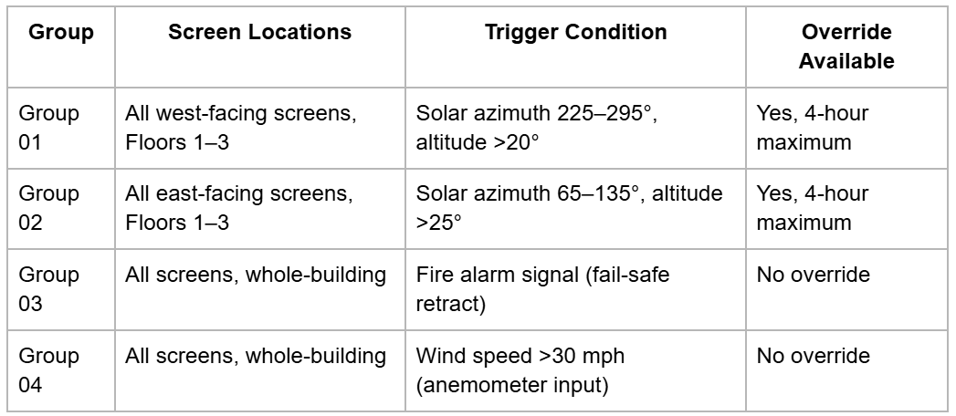
This table format, included in both the motorized screen specification section and the BAS/smart home specification section, ensures that the group address structure is understood by all contractors before bidding and before any programming begins.
Wiring Documentation Standards for the Low-Voltage System Submittal
The motorized screen control system wiring must be fully documented in the construction documents before permit submission. The low-voltage systems drawing package for a motorized screen project must include the following elements.
Control System Riser Diagram
The riser diagram provides a schematic overview of the entire control system topology from the control platform (smart home hub, BAS controller, or standalone timer) through the network cables, motor controllers, and motors. It shows every device in the system, the protocol and cable type connecting each device, the power supply locations, and the signal flow direction for commands and feedback.
The riser diagram does not show physical routing; that is the function of the floor plan drawings. The riser diagram shows the logical architecture of the system, enabling any engineer reviewing the documents to understand how every component relates to every other component without referring to multiple drawings.
Floor Plan Low-Voltage Symbol Legend
All motorized screen control system components shown on floor plans must use a consistent symbol set drawn from the project's low-voltage symbol legend. At minimum, the legend must define symbols for: motor location, motor control panel/enclosure, wall switch, hub/controller location, RS-485 or KNX bus cable run, line-voltage motor power feed, and smart home bridge device location.
Point-to-Point Wiring Diagram
For each motor zone, a point-to-point wiring diagram must show terminal-by-terminal the wiring between the motor's wiring harness, the motor control panel or controller module, the wall switch, the RS-485 bus connection or relay interface, and the power supply. Terminal designations must match the motor manufacturer's published wiring diagram.
Relying on the motor manufacturer's generic installation guide as a substitute for project-specific point-to-point wiring drawings is a specification gap that generates inconsistent installation quality across multi-motor projects and complicates troubleshooting when field problems arise.
Commissioning Verification Checklist for Motorized Screen Control Systems
Before the control system is turned over to the owner, the commissioning engineer must verify each of the following items. This checklist should be included in the project's commissioning plan and signed off at substantial completion.
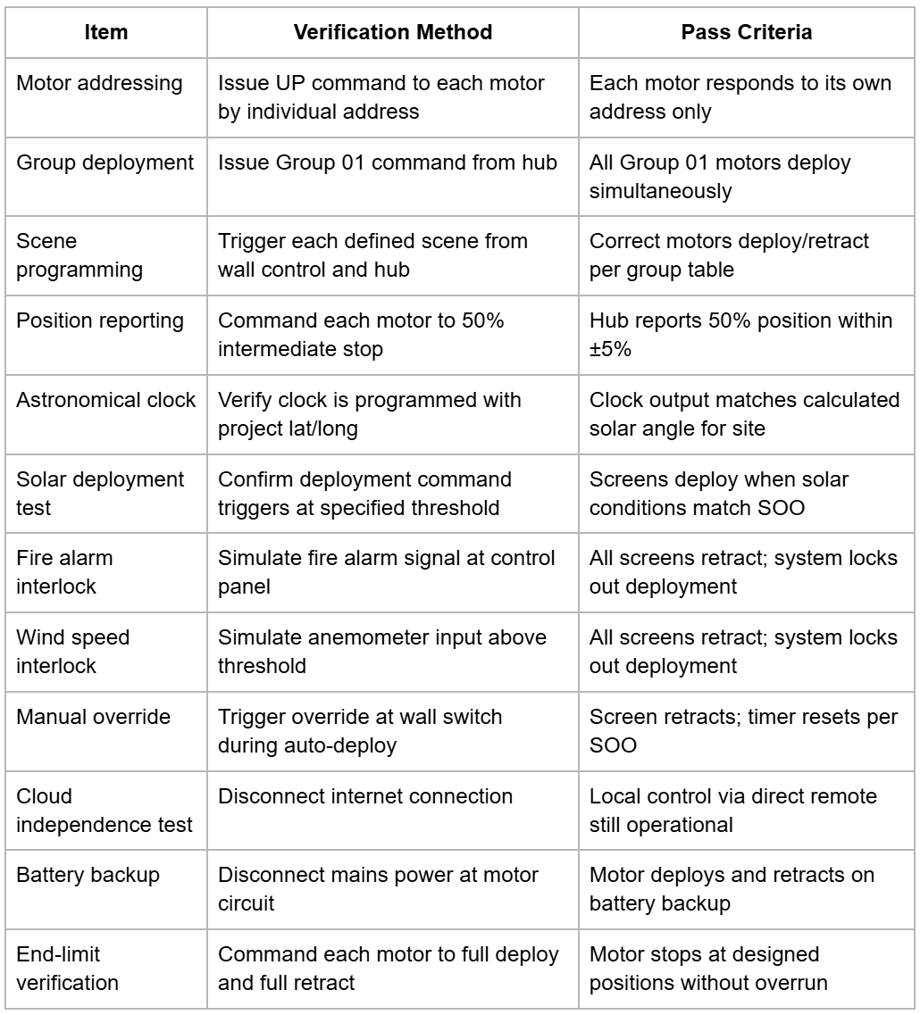
The Next Gen Screens blog series provides complementary engineering references across the full series, including motor torque and electrical specification data (Blog 4), commercial BAS integration protocols and sequence of operations documentation (Blog 6), and structural attachment standards for motorized screen systems (Blog 10).
Conclusion: Automation Integration Is a Specification Discipline, Not a Field Activity
Motorized screen automation integration fails in the field when it was not specified on the drawings. Missing protocol documentation means installers make protocol choices independently, resulting in systems that cannot be integrated with the owner's platform. Missing wiring diagrams mean electricians wire motors to informal field sketches that differ between installers and between zones. Missing commissioning checklists mean the system is handed over without verified function, and service calls begin within weeks.
The technical discipline required to produce a complete motorized screen automation specification is not greater than the discipline required for any other low-voltage system in the construction documents. It requires protocol selection, topology documentation, wiring standards compliance, group address planning, and a commissioning verification checklist. Applied systematically on every project, it produces control systems that function correctly at turnover and continue functioning through the full service life of the screens.
Need control system documentation, wiring diagrams, or protocol specification resources for your current project? The engineering library at Next Gen Screens provides technical documentation organized for the professional workflow. Access the full resource library at nextgenscreens.com.