How to Integrate Motorized Screens into Architectural Drawings: CAD Standards and Design Protocols
Why Motorized Screens Must Appear in the Construction Document Set
The most consistent source of motorized screen installation problems is not product failure and it is not installer error. It is the absence of the screen from the construction document set until after structural framing is complete.
When a motorized screen system is treated as a finish-phase add-on rather than a designed building component, the consequences are predictable: header pocket framing does not exist or is undersized, electrical rough-in is missing from the motor location, sill conditions are not coordinated with the track system, and the product approval documentation arrives at the building department without the backing of a properly prepared submittal package. Each of these failures is correctable in the field, but none are inexpensive to correct.
Architects who integrate motorized screen specifications into their construction documents from schematic design forward eliminate this class of problem entirely. The screen cassette housing dimensions drive header pocket framing requirements. The track attachment method drives substrate preparation notes. The motor location drives electrical coordination. All of these dependencies are resolvable at the drawing board; none of them are resolvable gracefully in the field.
This guide provides the architectural drawing protocols, CAD standards, detail requirements, and specification section guidance that allow motorized screens to be fully integrated into any project type: residential, commercial, or mixed-use. The complete technical resource library at Next Gen Screens supports this process with product-specific dimensional data, installation details, and submittal documentation.
CAD Layer Standards for Motorized Screen Elements
Consistent layer naming and organization are the foundation of a coordinated construction document set. When motorized screen elements are placed on clearly named, logically organized layers, every consultant on the project team, including structural engineers coordinating header framing and MEP engineers routing electrical, can isolate and reference the screen information without ambiguity.
Recommended Layer Structure
The following layer naming convention is consistent with the AIA CAD Layer Guidelines, which organize layers using the format A-[Major Group]-[Minor Group]-[Status]. Motorized screen elements fit within the building envelope major group and should be organized as follows:
A-GLAZ-SCRN: Motorized screen components in plan and elevation views. This layer contains the screen housing outline, track lines, and sill channel in plan view, as well as the cassette housing profile and fabric drop extent in elevation views.
A-GLAZ-SCRN-DTLS: Motorized screen detail references and detail bubbles. All enlarged details related to screen header, track, and sill conditions are referenced from this layer.
A-ELEC-SCRN: Electrical coordination elements for motorized screen motor locations. Power supply points, conduit stubs, and low-voltage wiring pathways for screen motors are placed on this layer for MEP coordination.
A-ANNO-SCRN: Annotation, keynotes, and specification callouts specific to motorized screen elements.
A-EQPM-SCRN: Motor and control equipment symbols in plan, including wall control locations and smart home integration junction points.
Layer Color and Line Weight Assignment
Motorized screen elements should be visually distinguishable from glazing and door elements in the document set to prevent coordination errors during drawing review. The following assignments are consistent with industry drawing standards:
Screen cassette housing outline: medium line weight (0.35 mm), screened at 50 percent in plan view to distinguish from structural elements
Screen track lines in plan: thin line weight (0.18 mm), dashed where concealed within wall assembly
Electrical coordination elements: thin line weight (0.18 mm), on the electrical layer, in a distinguishing color assigned to MEP coordination
Exterior Elevation Drawing Requirements
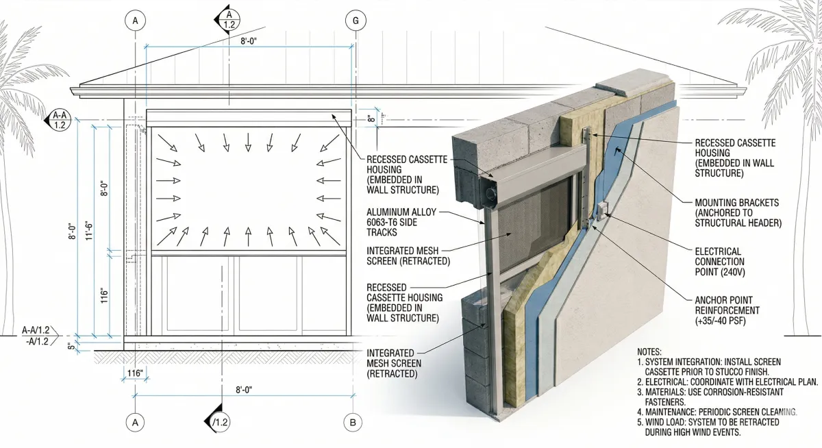
The exterior elevation is where motorized screen integration becomes visible to the entire project team and to the building official reviewing the permit application. Elevation drawings must communicate three things about each motorized screen location: the cassette housing position, the deployed screen extent, and the relationship of the screen system to adjacent building elements.
Cassette Housing Representation
The motorized screen cassette housing mounts above the opening it serves. In the elevation drawing, the cassette housing should be represented as a solid rectangle at the head of the opening, with dimensions indicated. Typical cassette housing heights range from 5 inches to 9 inches depending on the screen width and fabric weight; architects must obtain the specific cassette dimensions from the manufacturer's product data sheet for the system being specified and use those dimensions in the drawing rather than assumed values.
The cassette housing representation in elevation should include:
Overall cassette width (matching the clear opening width plus the track projection on each side)
Cassette height (obtained from the product data sheet)
Cassette projection from the building face (typically 3 inches to 5 inches for residential systems; deeper for commercial systems with wider spans)
A note indicating "Motorized Screen Cassette Housing, See Detail [X/X] and Specification Section [X]"
Deployed Screen Extent
The deployed screen position should be indicated in elevation using a dashed line or a screened solid representation, showing the full fabric drop from the cassette sill to the screen's deployed bottom edge. For screens that deploy to grade, the sill anchor point should be called out. For screens that deploy to a structural sill channel, the channel location should be indicated with a section reference.
Indicating the deployed screen extent in elevation serves a dual purpose: it confirms that the screen opening coverage matches the architectural intent, and it identifies any adjacent elements (door handles, light fixtures, hose bibs, structural columns) that may conflict with the deployed screen position and must be relocated.
Track Lines in Plan
In the floor plan, the two side tracks of the motorized screen system should be indicated as thin lines running the full height of the opening in the exterior wall. The track projection from the wall face, typically 1.5 inches to 2.5 inches for aluminum extrusion systems, must be noted to allow furniture placement and accessible route clearance to be confirmed.
Header Pocket and Sill Detail Requirements
The two most structurally consequential details in any motorized screen integration are the header condition and the sill condition. Both must be drawn and dimensioned with sufficient precision to allow the structural engineer to confirm framing adequacy and the installer to execute the work without field interpretation.
Header Pocket Detail
The header pocket is the recessed cavity above the opening that receives the motorized screen cassette housing. For concealed installations (where the cassette is housed within the wall assembly), the pocket must be framed to the following minimum clearances:
Pocket width: Clear opening width plus 2 inches minimum on each side for track mounting flanges and structural anchors
Pocket height: Cassette housing height plus 1 inch minimum clearance for installation access; confirm with the specific product's installation manual
Pocket depth: Cassette housing depth (projection from wall face) plus 0.5 inch minimum; this determines the reveal at the face of the wall assembly
The header pocket detail should be drawn at a minimum scale of 1.5 inches to 1 foot (1:8) and should show:
Framing members (header beam or lintel) with section dimensions called out
Pocket finish surface material (stucco, paint-grade wood, aluminum trim angle)
Cassette housing outline in dashed line
Motor service access clearance note
Structural anchor locations with a note directing to the product approval installation details
Reference to the product approval number or NOA number
For exposed installations (where the cassette is surface-mounted above the opening rather than recessed), the header detail must show the mounting substrate, the anchor pattern, and the relationship of the cassette face to the building's finished exterior surface.
Sill Detail
The sill condition varies by screen type and application. Architects must coordinate with the manufacturer's installation documentation to determine the appropriate sill configuration for each installation location.
Sill channel installations: A recessed aluminum channel is set into the finished floor or sill surface to receive the deployed screen's bottom edge. The sill channel detail must show the channel profile dimensions, the substrate preparation for the channel anchor, and the flush transition between the channel and the finished floor surface. ADA accessible route requirements apply if the channel crosses a path of travel: refer to ICC A117.1-2017 for threshold and change-in-level requirements at accessible routes.
Deployments to grade: Where screens deploy to grade level on exterior surfaces, the sill detail must address drainage at the screen's deployed base position and the relationship of the fabric edge to the finished grade or paving surface.
Specifying Motorized Screens for Your Next Project?
One Track's technical documentation includes CAD-ready details, product approval data sheets, and specification section templates formatted for architect submittal packages. Explore One Track's professional resources at onetrackscreens.com
Window and Door Schedule Integration
The window and door schedule is the primary specification reference for exterior opening components in a construction document set. Motorized screens should be included in the schedule as a separate component type, not embedded as a note within a window or door entry. A dedicated motorized screen column or a separate motorized screen schedule section prevents the screen specification from being overlooked during contractor bidding and permit review.
Motorized Screen Schedule Fields
The following fields should appear in the motorized screen schedule:

The product approval number and design pressure rating fields are mandatory for any project in a Florida jurisdiction and should be treated as mandatory for any project in a wind-borne debris region regardless of state.
Specification Section Placement: CSI MasterFormat
Motorized screens are specified under CSI MasterFormat 2020 in one of two sections depending on the project's specification organization and the primary function of the screen system:
Division 10 28 00: Exterior Sun Control Devices This section is appropriate when the motorized screen's primary design function is solar control, glare reduction, or thermal performance. The section covers exterior louvers, sun shades, and motorized screen systems used for shading and energy management applications.
Division 08 71 00: Door Hardware This section is occasionally used for motorized screen systems integrated with door and window assemblies in commercial projects, particularly when the screen system is specified as part of a larger opening protection or curtain wall scope.
Division 08 44 00: Curtain Wall and Glazed Assemblies For large-scale commercial projects where motorized screens are integrated into a curtain wall or storefront system, coordination with the glazing specification under Division 08 44 is required. The screen specification may appear as a separate section or as a sub-section within the curtain wall specification depending on procurement method.
Minimum Specification Section Content
Regardless of the section location, the motorized screen specification must include the following content to support compliant installation and permitting:
Part 1: General
Summary of work, related sections, references (ASTM E330, ASTM E1886/E1996 where applicable, Florida Building Code, ASCE 7-22)
Product approval or NOA requirements; statement that installation must comply with the approval document
Submittals: product data sheets, shop drawings, product approval or NOA documentation, motor wiring diagrams, fabric samples
Part 2: Products
Manufacturer and product model
Cassette housing material, finish, and profile dimensions
Track system: material, extrusion profile, Keder groove dimensions where applicable
Fabric: manufacturer, product name, openness factor, UV transmittance, color
Motor: manufacturer, model, torque rating, voltage, IP rating, operating temperature range
Controls: type (hardwired wall switch, remote receiver, smart home interface), protocol specification
Part 3: Execution
Installer qualifications: reference to manufacturer's authorized installer network
Examination: substrate preparation requirements per the product approval installation document
Installation: sequence, anchor schedule, dimensional tolerances
Adjusting: screen alignment, end-limit adjustment, motor torque calibration
Cleaning and protection: fabric care instructions, cassette housing cleaning
Architects specifying motorized screens for projects involving hurricane-rated performance in the HVHZ should coordinate the specification with Max Force Hurricane Screens to confirm that the system selected carries the applicable Miami-Dade NOA and that the specification section references the TAS 201/202/203 testing standards accurately.
Submittal Package Preparation
The motorized screen submittal package is a critical document for the building department review process and for the contractor's installation coordination. Architects should establish submittal requirements early in the project and confirm that the package is complete before permit submission.
Required Submittal Documents
Product Data Sheet: Manufacturer's published data sheet showing cassette dimensions, track profile, motor specifications, fabric options, approved sizes and configurations, and product approval or NOA reference. Confirm that the model number on the data sheet matches the model number in the schedule.
Product Approval or NOA Document: The complete Florida Product Approval document or Miami-Dade NOA, downloaded from the Florida Building Commission product approval database or the Miami-Dade County product search portal. The approval document includes the installation details that are the required installation reference for inspectors; a manufacturer's marketing brochure does not substitute for the approval document.
Shop Drawings: Dimensioned installation drawings showing the cassette position, track layout, anchor locations, and coordination with adjacent construction for each screen location. Shop drawings should be prepared by the manufacturer or the authorized installer and reviewed by the architect against the construction documents.
Motor Wiring Diagram: Electrical diagram showing the motor wiring configuration, power supply requirements, and control system connections. This document coordinates with the electrical engineer's submittal.
Fabric Sample: Physical sample with the manufacturer's product name, openness factor, and color designation clearly labeled. Required for architect review and owner approval.
The Next Gen Screens blog series provides additional specification and coordination resources for architects working with motorized screen systems across project types.
Coordination Protocol with Structural and MEP Engineers
Motorized screens generate structural and electrical coordination requirements that must be communicated to the project's consulting engineers in a timely and precise format. The following coordination protocol establishes the minimum information that must be transmitted to each consultant and the appropriate timing within the project schedule.
Structural Engineer Coordination
Information to transmit: Header pocket dimensions and framing requirements per the product approval installation details; any locations where screens span openings greater than 12 feet (large spans require anchor load calculations); substrate type at each screen location.
Timing: Issue structural coordination information no later than the Design Development phase. Header framing requirements must be incorporated into the structural drawings before the permit set is issued.
Reference document: The product approval installation details, which specify minimum header dimensions, anchor types, and fastener schedules for the approved substrate types.
MEP Engineer Coordination
Information to transmit: Motor locations, power supply voltage (typically 120V AC), amperage draw per motor, conduit stub-out position relative to motor centerline, and any low-voltage wiring requirements for smart home or building automation integration.
Timing: Issue electrical coordination information no later than the Construction Documents phase, before the electrical engineer completes the electrical panel schedules. Motor circuits must appear on the panel schedule in the permit set.
Reference document: The motor manufacturer's wiring diagram and the product data sheet electrical specifications.
Conclusion: Coordination at the Drawing Stage Eliminates Field Problems
Motorized screens are a designed building component. Their integration into a project's construction documents requires the same discipline applied to any other exterior opening system: dimensional coordination, structural consultation, electrical planning, and specification preparation. When this work is completed at the drawing stage, the installation proceeds without structural surprises, inspection complications, or permit submission delays.
The specification protocols described in this guide are consistent with standard architectural practice and with the product approval requirements that govern motorized screen installation in permitted construction. Applying them systematically across every project where motorized screens appear will produce coordinated, code-compliant construction documents.
Looking for CAD-ready details and specification templates for your next project? The technical resource library at Next Gen Screens is built for the professional workflow. Access product data, installation details, and specification documentation at nextgenscreens.com.