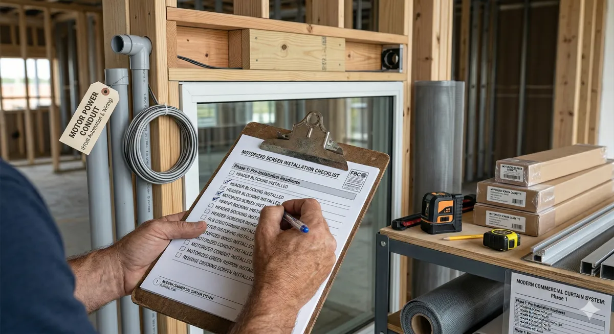
Motorized Screen Installation Sequence: Pre-Construction Coordination, Rough-In, and Final Integration
Why Motorized Screen Installation Problems Begin Before the Installer Arrives
The motorized screen installer who arrives on a completed project to find that the header pocket framing is missing, the electrical conduit stub-out is 6 inches from where the motor needs it, and the masonry cores beneath the track anchor locations have not been grouted is not encountering installation problems. He is encountering pre-construction coordination failures that materialized weeks earlier, when the structural framing and electrical rough-in were completed without the motorized screen installation requirements built into the scope.
This pattern accounts for the majority of rework, schedule delays, and change order costs associated with motorized screen installations on permitted projects. The installer cannot fix a header that was not framed to the right dimensions without a general contractor authorization to cut into finished framing. The electrician cannot relocate a conduit stub-out that is already in a finished wall without opening drywall. The masonry contractor cannot grout block cores that have already been covered without demolishing and rebuilding a section of wall.
Each of these corrections costs more in schedule time and labor than the coordination that would have prevented them. The correct approach is to treat motorized screen installation as a phased scope that begins in pre-construction, has defined milestones at structural rough-in and electrical rough-in, requires substrate verification before ordering product, and concludes with a documented commissioning procedure before the screen system is handed to the owner.
This guide provides builders with the complete phase-by-phase installation sequence. The technical resource library at Next Gen Screens provides product-specific dimensional data, installation details, and coordination checklists to support each phase.
Phase 1: Pre-Construction Coordination
Pre-construction coordination for motorized screens must begin no later than the design development phase and must be completed before structural framing begins. The goal of this phase is to confirm that every element of the structure that will receive or support the motorized screen system is designed, detailed, and communicated to the trades before their work begins.
Confirming Product Selection and Dimensional Data Before Framing
The single most important pre-construction coordination task is confirming the specific motorized screen product and obtaining its published dimensional data before the structural framing is designed. The header pocket framing dimensions, the track mounting depth from the wall face, and the sill condition all depend on product-specific measurements that cannot be assumed from generic specifications. Different manufacturers' products have different cassette housing heights, different projection depths from the wall face, and different track profile dimensions. Framing to the wrong dimensions and then discovering the error when the product arrives is a preventable and costly mistake.
Pre-construction dimensional data required from the manufacturer or authorized installer before framing begins:
Cassette housing height (H): the vertical dimension of the cassette as it will be seen at the face of the wall
Cassette housing depth (D): the projection of the cassette from the mounting surface toward the exterior
Motor service access clearance: the minimum clearance above and to the side of the cassette required for motor removal without disturbing adjacent construction
Track profile width: the width of the aluminum extrusion as mounted, including any mounting flanges
Track projection from wall face: the distance the track extends from the finished wall surface into the opening
Sill channel profile dimensions: width, depth, and height of the recessed sill channel if applicable
These dimensions are available in the product manufacturer's installation manual and product data sheet. They should be incorporated into the architectural drawings before the structural framing drawings are finalized.
Communicating Requirements to the Structural Framing Contractor
The structural framing contractor must receive explicit written instructions for the following conditions at each motorized screen location before framing begins:
Header pocket dimensions: The pocket receiving the cassette housing must be framed to minimum dimensions that provide the cassette housing height plus a minimum 1-inch clearance above for installation access, plus the motor service access clearance specified by the manufacturer. The pocket width must equal the clear opening width plus the track mounting flange width on each side plus the anchor edge distance specified in the product approval installation details.
Blocking and structural support: Where the cassette housing is surface-mounted to a wood frame wall rather than recessed into a pocket, the mounting location requires solid blocking between studs sufficient to carry the cassette dead load and the transferred wind load. The blocking member dimensions and species must be specified per the product approval installation details or per the project's structural engineer's calculations for large-span applications.
Masonry core fill locations: Where the screen is being installed on a concrete masonry unit (CMU) wall and the product approval installation details require grouted cores at anchor locations, the masonry contractor must be provided with anchor location drawings before the masonry is laid. Grouting cores after the masonry is complete requires drilling, which is less reliable than grouting during construction.
Sill channel rough-in: Where a recessed sill channel is specified, the floor contractor must be provided with the channel's profile dimensions and its exact position relative to the wall face before the floor substrate is placed. The channel must be set at the correct depth to finish flush with the completed floor surface.
Communicating Requirements to the Electrical Contractor
The electrical contractor must receive the following information before electrical rough-in begins:
Motor location: the exact position of the motor within the cassette housing, expressed as a dimension from the left or right track centerline (varies by manufacturer and product model; confirm from the installation manual)
Conduit stub-out position: the required position of the conduit stub-out relative to the motor centerline, expressed as horizontal and vertical offsets; this is motor-specific and must be confirmed from the manufacturer's rough-in drawing
Conduit size: the minimum trade size of conduit required for the motor's wiring harness (typically 1/2-inch for residential motors; confirm from the motor data sheet)
Circuit type: 120V AC dedicated or shared circuit, with circuit protection size per the motor's full-load current and NEC Article 430 requirements (reference Blog 4 of this series for circuit sizing methodology)
Low-voltage wiring requirements: if smart home or BAS integration is specified, the low-voltage bus cable routing, conduit requirements, and junction box locations must be included in the electrical rough-in scope
Phase 2: Structural Rough-In Verification
Before drywall or finish materials are applied and before the motorized screen product is ordered, a structural rough-in verification inspection must confirm that all framing and substrate conditions match the product's installation requirements. This verification is the builder's opportunity to identify and correct any discrepancies while the structure is still accessible without demolition.
Header Pocket Verification
At each motorized screen location, verify the following against the product data sheet and product approval installation details:
Pocket height: Measure the clear height of the header pocket from the finished header face to the top of the pocket. Confirm it equals or exceeds the cassette housing height plus the manufacturer's required installation clearance. Record the actual dimension and compare it to the required minimum. If the pocket is undersized, the framing must be modified before drywall.
Pocket width: Measure the clear width of the header pocket. Confirm it equals or exceeds the required minimum. A pocket that is too narrow prevents the cassette from being inserted horizontally during installation and cannot be corrected after drywall without opening the wall.
Pocket depth: Measure the depth of the pocket from the wall face. Confirm it accommodates the cassette housing depth with the required clearance. A pocket that is too shallow will cause the cassette to project beyond the wall face plane, creating a visible aesthetic inconsistency and potentially conflicting with adjacent trim elements.
Structural member: Confirm that the structural element at the top of the pocket (header beam, lintel, or concrete band) is the member specified in the product approval installation details for the anchor type and spacing being used. A header framed from dimensional lumber where a laminated veneer lumber (LVL) header was specified in the product approval may not have sufficient capacity for the applied anchor loads.
Electrical Rough-In Verification
At each motor location, verify:
Conduit stub-out position: Confirm that the conduit stub-out is located within the manufacturer's specified tolerance zone relative to the motor centerline. Most manufacturers specify a tolerance zone rather than an exact point because motor positions can vary slightly within the cassette assembly. Confirm the tolerance zone from the installation manual before verifying; a stub-out that appears misaligned by 2 inches may be within the manufacturer's acceptable range.
Conduit size and type: Confirm conduit trade size, type (EMT, LFMC, Schedule 80 PVC), and that the conduit terminates with an appropriate connector at the stub-out location that will accept the motor's wiring harness.
Circuit presence: Confirm that the motor circuit conductor is present in the conduit and that the circuit is identified at the panel with the motorized screen zone it serves. Unlabeled circuits discovered during motor commissioning create unnecessary troubleshooting delays.
Low-voltage wiring: If RS-485 bus, KNX TP, or other low-voltage control wiring is specified, confirm that the cable is present in the designated conduit or raceway, properly routed from the motor location to the control panel or hub location, and labeled at both ends.
Building a Motorized Screen Project and Need Installation Documentation?
One Track provides builders with product-specific rough-in guides, header pocket detail drawings, and installation sequence checklists formatted for field use. Access One Track's builder installation resources at onetrackscreens.com
Phase 3: Product Ordering and Lead Time Management
Motorized screen systems are custom-manufactured products. The cassette housing is fabricated to the specific clear opening width. The fabric is cut to the specified width and drop. The motor is selected for the specific torque requirement based on the fabric weight and screen dimensions. None of these components are stocked in standard sizes that can be substituted or expedited from inventory.
Lead Time Realities for Builders
Residential motorized screen systems from quality manufacturers typically carry fabrication lead times of 3 to 6 weeks from the date of confirmed order. Commercial systems with large-span configurations or specialty fabrics may carry 6 to 10 weeks. These lead times are from confirmed order, not from quote approval: the fabrication clock does not start until the manufacturer has received signed approval drawings, confirmed dimensions, and a purchase order.
Builders who treat motorized screen ordering as a finish-phase task, placing the order after drywall is complete and finish work has begun, will find that the screens cannot be installed before the certificate of occupancy inspection unless the fabrication window falls within the remaining project schedule. The correct approach is to place the product order after the rough-in verification is complete and confirmed, which is typically the earliest point at which opening dimensions can be confirmed as built within the manufacturer's allowable dimensional tolerances.
Confirming As-Built Dimensions Before Ordering
Product dimensions for motorized screens are typically specified as clear opening width and drop height. The clear opening width is measured from the inside face of the left track mounting location to the inside face of the right track mounting location. This is not the rough opening width; it is the net clear dimension after accounting for the track mounting flange projection into the opening on each side.
The builder must confirm as-built clear opening dimensions by field measurement after framing is complete and before ordering product. Dimensions taken from drawings may differ from as-built conditions by 1/4 inch to 1/2 inch, which is within normal construction tolerance but may affect product fabrication if the manufacturer's tolerances are tighter. Confirm allowable dimensional tolerances with the manufacturer before field measurement and before ordering.
Phase 4: Track and Cassette Mounting
Track and cassette mounting is the most precision-dependent phase of the motorized screen installation. Errors in track plumb, track-to-track parallelism, and cassette level cannot be corrected after the fabric is installed without removing the cassette and restarting the track mounting sequence. The builder's role in this phase is to confirm that site conditions support precision installation and that the installer has access to the information needed to execute the installation correctly.
Track Plumb and Parallelism Tolerances
Both side tracks must be plumb (vertical) within the manufacturer's specified tolerance, and both tracks must be parallel to each other within the manufacturer's specified tolerance across the full deployed height of the screen. Most manufacturers specify a maximum out-of-plumb tolerance of 1/8 inch per 8 feet of track height and a maximum track-to-track parallelism tolerance of 3/16 inch across the full span.
These tolerances exist because the Keder bead along the fabric edge must move smoothly through the track groove during deployment and retraction. A track that is out of plumb creates a varying contact geometry between the Keder bead and the groove that generates uneven friction, causes the fabric to develop tension asymmetry across its width, and can cause the motor's end-limit switch to trigger prematurely or inconsistently. A track-to-track parallelism error creates a condition where the fabric is under differential tension from left to right, which over time causes the bottom bar to travel off-level and the fabric to develop a visible diagonal tension crease.
The installer verifies plumb with a digital level or precision plumb bob, not a standard 2-foot carpenter's level. The builder's responsibility is to confirm that the mounting surface is flat and accessible and that any surface irregularities that would prevent the track from seating flush have been identified and corrected before the installer arrives.
Cassette Level and Alignment
The cassette housing must be mounted level within the manufacturer's specified tolerance (typically 1/8 inch over the full cassette length). An out-of-level cassette causes the fabric to travel at a slight angle during deployment, producing progressive tracking errors that worsen over repeated deployment cycles and can eventually cause the Keder bead to ride partially out of the track groove at the cassette exit point.
Where the cassette is surface-mounted, the mounting surface must be flat and free of projections. Where the cassette is recessed into a header pocket, the mounting surface inside the pocket must be flat and level. High spots or irregularities in the pocket bottom surface require shimming at the cassette mounting points to achieve the specified level tolerance.
Substrate Verification at Anchor Locations
Before drilling anchor holes, the installer must confirm substrate type and condition at each anchor location. The product approval installation details specify the anchor type, diameter, length, and minimum embedment depth for each approved substrate. The installer must use the anchor specified for the actual substrate present, not a substitute of comparable size.
Common substrate verification errors that generate non-compliant installations:
Hollow CMU cores: Where the product approval requires solid masonry or grouted cores and the installer encounters hollow cores at the anchor location, the correct response is to stop and report the condition to the general contractor before proceeding. Filling hollow cores with hydraulic cement after the fact as a field fix is not an approved substitute for the masonry core fill specified in the product approval.
Wood stud miss: Where tracks are being anchored to a wood frame wall and the installer's anchor location does not align with a stud or the specified blocking, anchoring into sheathing or exterior cladding is not compliant. The general contractor must confirm blocking location before installation proceeds.
Concrete substrate variation: Where concrete substrates vary in compressive strength, anchor capacity can vary significantly. If the installer encounters evidence of lightweight or low-strength concrete (by visual or drill feel), the anchor selection specified in the product approval for standard concrete may not achieve the specified pullout capacity. The condition should be reported before proceeding.
Phase 5: Motor Wiring and Control System Connection
Once the cassette is mounted and the tracks are verified plumb and parallel, the motor wiring is connected and the control system integration is completed before the fabric is loaded and end-limit switches are set.
Motor Wiring Connection Sequence
The motor wiring connection must follow the manufacturer's published wiring diagram. Incorrect wiring polarity will cause the motor to rotate in the wrong direction, driving the cassette reel in the deployment direction on a retract command and vice versa. This error is detectable during commissioning and correctable by swapping the UP and DOWN conductors, but it requires access to the wiring connections and should be verified before the wall access point is closed.
Standard verification sequence before loading the fabric:
Apply power to the motor circuit with the motor in the cassette but with no fabric loaded on the reel
Issue an UP command from the wall switch or control interface
Confirm the reel rotates in the direction that would retract the fabric (upward winding on the reel)
Issue a DOWN command and confirm the reel rotates in the deployment direction
If rotation direction is reversed from expected, swap the UP and DOWN conductor connections at the motor control panel or wall switch wiring
This sequence is faster to execute before the fabric is loaded than after, because a fabric loaded on a reel that winds in the wrong direction must be removed from the reel before the wiring correction can be made.
Control System Commissioning at Motor Connection
Where smart home or BAS integration is specified, the control system must be verified functional at the motor connection phase before the fabric is loaded. Commissioning protocol varies by control protocol (reference Blog 7 of this series for the 12-point commissioning verification checklist), but the minimum verification at this phase is:
Motor responds to UP and DOWN commands from the control interface
Motor address is confirmed in the control system (for SDN, KNX, or Z-Wave addressed systems)
Wiring continuity is confirmed at every junction in the low-voltage control circuit
Phase 6: Fabric Loading, End-Limit Setting, and Final Commissioning
The final installation phase covers fabric loading onto the reel, end-limit switch setting, deployment and retraction testing, and final commissioning sign-off.
Fabric Loading
Fabric loading is a two-person operation for screens with deployed heights greater than 8 feet. One installer manages the cassette end while a second guides the fabric as it unrolls and feeds the Keder bead into the track groove. The Keder bead must be fully seated in the track groove along the entire length of both sides before the motor is used to deploy or retract the screen for the first time.
A partially seated Keder bead pulled through the track by motor force is the most common cause of track damage during installation. The track groove's entry section is beveled to guide the Keder bead into the groove, but the bead must be fed by hand through the first 12 to 18 inches of each track from the cassette exit point before motor-driven movement begins.
End-Limit Switch Setting
End-limit switches define the motor's stop positions at full deployment (bottom of travel) and full retraction (top of travel). Most tubular motors for motorized screens use electronic end-limit switches that are set by the installer during commissioning using a button sequence or a remote control sequence specified in the motor manufacturer's installation guide.
The bottom end-limit is set with the screen at the designed deployed position: fabric fully extended, bottom bar at the sill channel or at the specified clearance above the finished floor. The top end-limit is set with the fabric fully retracted into the cassette housing, with sufficient wind on the reel to prevent the fabric from drooping out of the cassette opening when the screen is retracted.
Incorrect end-limit settings are the most common cause of motor warranty claims in the first year of service. A bottom end-limit set below the actual sill contact position will cause the motor to continue driving the reel after the bottom bar has contacted the sill, generating stall torque loads that exceed the motor's rated capacity and accelerate gear wear. A top end-limit set with insufficient wind on the reel will allow the fabric to partially exit the cassette when retracted, resulting in wind noise in the deployed position and fabric exposure to UV when retracted.
Final Deployment and Retraction Testing
Before sign-off, the installer must complete a minimum of three full deployment and retraction cycles and confirm:
Bottom bar travels to the designed stop position consistently on each cycle
Motor stops cleanly at both end-limit positions without overrun
Fabric surface is free of creases, tension ridges, or diagonal stress marks that would indicate track alignment issues
Keder bead remains fully seated in both tracks throughout the full travel range
Deployment speed is consistent from fully retracted to fully deployed without hesitation or variation
Retraction speed is consistent through the full travel range
Any inconsistency detected during testing must be resolved before the installation is accepted and before the inspection record is completed.
Builder Acceptance Checklist Before Owner Turnover
Before the motorized screen installation is turned over to the owner, the builder must confirm:
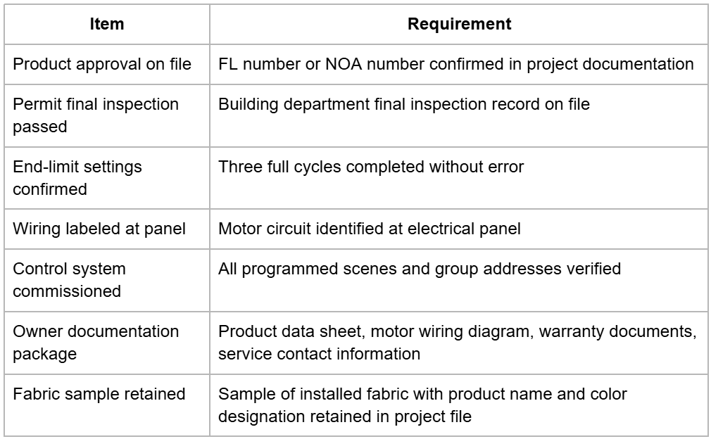
For projects requiring hurricane-rated performance, the builder must also confirm that the product approval or NOA documentation, the installation record, and the permit final inspection record are all available for the wind mitigation inspector. Builders specifying hurricane-rated systems in the HVHZ should coordinate final documentation with Max Force Hurricane Screens to confirm that HVHZ-specific NOA installation compliance documentation is complete.
The Next Gen Screens blog series provides complementary builder resources across the series, including wind load specification methodology (Blog 1), Florida Building Code compliance and permit documentation (Blog 5), and structural attachment standards for diverse substrates (Blog 10).
Conclusion: Installation Quality Is Determined in Pre-Construction, Not at Punch List
The motorized screen installation sequence is not a single-trade task that happens after finish work is complete. It is a multi-phase coordination effort that spans pre-construction, structural rough-in, electrical rough-in, substrate verification, product ordering, mounting, wiring, and commissioning. Each phase has defined deliverables that must be completed correctly before the next phase can proceed without risk of rework.
Builders who manage the motorized screen installation sequence as a coordinated scope with explicit phase deliverables produce installations that arrive at final inspection without non-compliance findings, pass commissioning on the first attempt, and are handed to the owner with complete documentation. Builders who treat motorized screens as a finish-phase subcontractor task without pre-construction coordination produce the change orders, inspection delays, and service calls that characterize the most expensive motorized screen installations in any project portfolio.
Need phase-specific installation documentation, rough-in guides, or acceptance checklists for your current project? The builder resource library at Next Gen Screens provides technical installation documentation organized by project phase. Access the full library at nextgenscreens.com.