Motor Torque Data and Load Requirements for Motorized Screen Systems
Motor Selection Is an Engineering Calculation, Not a Catalog Decision
The tubular motor inside a motorized screen reel tube is a mechanical actuator operating under a defined load in a defined environment. It has a torque rating expressed in Newton-meters (Nm), a rotational speed expressed in RPM, an electrical supply requirement expressed in voltage and current draw, a thermal protection class, and an environmental enclosure rating expressed as an IP code. Each of these parameters must be verified against the system's actual load and installation conditions before a motor is specified or approved.
Engineers who treat motor selection as a manufacturer-standard decision, accepting whatever motor the screen fabricator includes in the base specification without verifying it against project-specific load calculations, risk two classes of field failure: motors that are undersized for the actual load and stall under full deployment, and motors that are oversized and generate excess torque that stresses the fabric, the reel tube, and the end-limit switch mechanisms.
Neither failure mode announces itself during commissioning. Both manifest during operational use, typically when environmental conditions, fabric tension changes, or system aging push the motor beyond its operating range. The correct approach is to calculate the required torque from first principles, verify the specified motor's rated torque against that calculation with an appropriate safety factor, and confirm that the motor's electrical characteristics are compatible with the project's electrical system.
The technical resource library at Next Gen Screens provides product-specific motor data sheets to support this process.
Understanding the Tubular Motor: Architecture and Operating Principles
The tubular motor is the drive mechanism for virtually all motorized screen and roller shade systems in commercial and residential applications. Understanding its mechanical architecture is a prerequisite for correct load calculation and motor selection.
Physical Configuration
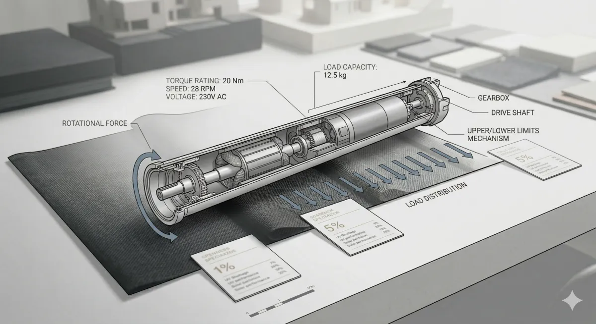
A tubular motor consists of a permanent magnet AC or DC motor, a multi-stage planetary gearbox, a thermal overload protector, and an end-limit switch mechanism, all housed within a cylindrical aluminum or steel tube. The motor assembly inserts into the hollow interior of the screen's reel tube (the aluminum extrusion around which the fabric winds). The motor's output shaft connects to one end of the reel tube via a crown and adapter assembly; the opposite end of the reel tube rests on a support bracket with an idle plug. When the motor rotates, the reel tube and the wound fabric rotate with it.
The planetary gearbox reduces the motor's rotational speed to a range typically between 12 RPM and 28 RPM at the output shaft, while multiplying torque from the motor's internal output to the rated working torque at the reel. The gear ratio is fixed for a given motor model; it is not field-adjustable.
Torque, Speed, and the Operating Curve
The motor's published torque rating is its maximum continuous working torque, expressed in Newton-meters (Nm). This is the torque the motor can sustain indefinitely during normal operation without triggering thermal protection or accelerating gear wear. It is not the motor's stall torque, which is higher, and it is not the motor's starting torque, which is the peak torque available at zero RPM during the initial moment of fabric movement.
For motorized screen applications, the relevant torque value for load calculations is the working torque, not the stall torque. Stall torque is relevant only as a confirmation that the motor will not be damaged if the screen encounters an obstruction that prevents full deployment.
Most quality tubular motor manufacturers, including Somfy, Gaposa, and Dooya, publish detailed motor data sheets that include working torque (Nm), stall torque (Nm), nominal speed (RPM), no-load current (A), full-load current (A), supply voltage and frequency, duty cycle, thermal class, and IP rating. Engineers should obtain and retain these data sheets as part of the project documentation package.
Duty Cycle
Duty cycle is the ratio of motor on-time to total cycle time, expressed as a percentage. A motor rated at a 4-minute duty cycle (common for residential tubular motors) can operate continuously for 4 minutes before requiring a rest period to dissipate heat. A 10-minute duty cycle motor is rated for longer continuous operation.
For standard motorized screen installations, the deployment time for a single screen rarely exceeds 60 to 90 seconds, making duty cycle a secondary consideration in most residential and light commercial projects. However, in commercial applications where multiple screens deploy simultaneously on a building automation command, and in hurricane-rated applications where all screens deploy in rapid sequence before a storm, duty cycle becomes a primary selection criterion. Engineers specifying systems with rapid sequential multi-screen deployment should verify that the motor's duty cycle accommodates the worst-case deployment sequence without triggering thermal protection mid-cycle.
Load Calculation: Determining the Required Torque
The required working torque for a motorized screen motor is the sum of the torques generated by all resistive forces acting on the reel tube during deployment. Four load components contribute to this total.
Load Component 1: Fabric Weight
The fabric's weight per unit area (g/m²), combined with the screen's total deployed area, determines the gravitational load that the motor must overcome to initiate and sustain upward retraction movement. The formula is:
T_fabric = (W_fabric × g × r_reel) / 1000
Where:
W_fabric = total fabric mass in grams (fabric weight per m² × deployed area in m²)
g = gravitational acceleration (9.81 m/s²)
r_reel = effective reel radius in meters (half the reel tube outer diameter plus half the wound fabric thickness at mid-roll)
1000 = unit conversion factor from gram-meters to Newton-meters
Note that the effective reel radius increases as fabric winds onto the reel during retraction. The maximum reel radius (fully wound) generates the maximum fabric torque and represents the worst-case condition for retraction. This condition must be used in the calculation, not the empty reel radius.
Load Component 2: Bottom Bar Weight
The weighted bottom bar at the deployed screen's lower edge adds a concentrated gravitational load at the end of the fabric drop. The torque contribution of the bottom bar is:
T_bar = (m_bar × g × L_drop) / 1000
Where:
m_bar = bottom bar mass in grams
g = gravitational acceleration (9.81 m/s²)
L_drop = full deployed length in meters
1000 = unit conversion factor
The bottom bar torque contribution is highest at the beginning of retraction (when the bottom bar is at its maximum distance from the reel) and decreases as the screen winds up. This is therefore not the worst-case condition for total torque but must be confirmed not to exceed the motor's starting torque at the initiation of retraction.
Load Component 3: Track Friction
The side tracks that guide the screen fabric introduce friction forces opposing the fabric's movement during both deployment and retraction. Track friction depends on the track profile geometry, the fabric edge (Keder bead) diameter and material, the contact length between the Keder bead and the track groove, and the tension in the fabric at the track contact points.
Track friction is not directly calculable from first principles without detailed track geometry data; it is typically expressed as a friction coefficient or an equivalent resistive torque value in the motor manufacturer's application engineering guidelines. As a conservative approximation for preliminary calculations, many motor manufacturers recommend adding 20 to 30 percent to the calculated fabric and bottom bar torque to account for track friction, before applying the safety factor.
Load Component 4: Wind Load Torque Contribution
In wind conditions, the deployed screen fabric experiences distributed aerodynamic pressure loads that are transferred through the Keder track retention system into the tracks and the reel tube. During deployment and retraction in wind, these aerodynamic loads add to the motor's resistive torque.
For standard solar screen and insect screen applications in normal weather conditions, the wind load torque contribution during deployment is manageable within the motor's normal working torque range, provided the motor has been sized with the recommended safety factor applied. However, for systems specified in high-wind exposure zones or for hurricane-rated systems that may be deployed as wind speeds are rising, the wind load torque contribution becomes a primary design consideration.
Engineers specifying hurricane-rated motorized screen systems for high-wind zone applications should reference the manufacturer's published wind-load motor sizing tables, which provide required torque values as a function of screen width, drop height, and design wind pressure. These tables account for the aerodynamic load distribution on the deployed fabric under wind conditions and are the appropriate basis for motor selection in wind-critical applications. For hurricane-rated screen systems in the HVHZ, coordination with Max Force Hurricane Screens provides access to product-specific wind-load motor sizing data validated through the Miami-Dade NOA testing process.
Applying the Safety Factor
The total required torque is the sum of all load components:
T_required = (T_fabric + T_bar) × 1.25 [friction allowance] × 1.25 [safety factor]
The 1.25 safety factor applied after the friction allowance accounts for:
Tolerance variations in fabric weight and bottom bar mass
Aging effects on track friction as Keder beads wear over time
Motor torque output variation at the low end of the manufacturer's tolerance band
Ambient temperature effects on motor performance in high-heat coastal environments
The selected motor's rated working torque must equal or exceed T_required. If the calculation yields a required torque that falls between two standard motor torque ratings in the manufacturer's product range, the engineer should select the next higher rating, not the nearest one.
Specifying Motorized Screen Motor Systems for Your Next Project?
One Track's technical documentation includes motor torque data sheets, load calculation worksheets, and electrical specification guides formatted for engineer submittals. Explore One Track's engineering resources at onetrackscreens.com
Electrical Requirements: Supply Voltage, Current Draw, and Circuit Design
Motorized screen motors are available in two primary electrical configurations: line-voltage AC motors (120V or 230V AC, 50/60 Hz) and low-voltage DC motors (typically 24V DC). Each configuration has distinct electrical design implications for the engineer coordinating the project's electrical system.
Line-Voltage AC Motors (120V AC)
The majority of motorized screen systems installed in North American residential and light commercial construction use 120V AC tubular motors. Key electrical parameters for circuit design are:
Full-load current: Typically 0.5A to 1.5A per motor for residential-scale systems (screen widths up to 16 feet). Larger commercial motors for wide-span applications may draw 2A to 4A. Confirm from the motor data sheet.
Starting current (inrush): Inrush current at motor start is typically 5 to 8 times the full-load current for a fraction of a second. This is relevant for circuit breaker selection and for arc-fault circuit interrupter (AFCI) compatibility. Consult the motor manufacturer's electrical guidance for AFCI compatibility; some motor types generate inrush signatures that nuisance-trip AFCI breakers.
Circuit sizing: Per NEC Article 430, motor branch circuits must be sized at 125 percent of the motor's full-load current rating. For a 1.0A motor, the minimum branch circuit ampacity is 1.25A; in practice, a dedicated 15A circuit serves a multi-motor installation of up to ten standard residential motors on a shared circuit, provided the total connected load does not exceed 80 percent of the circuit breaker rating.
Dedicated vs. shared circuits: For residential installations, multiple motors on a shared 15A or 20A circuit is standard practice provided load calculations confirm compliance. For commercial installations where simultaneous multi-screen deployment is a design requirement, dedicated circuits per zone or per motor grouping are recommended to prevent voltage drop during simultaneous starting.
Conduit requirements: Motor supply wiring run in exterior environments must comply with NEC Article 300 wet location wiring methods. For installations where the motor or its wiring is exposed to weather, use Type THWN-2 conductors in liquidtight flexible metallic conduit (LFMC) or Schedule 80 PVC conduit. The conduit stub-out at the motor location must be positioned per the motor manufacturer's rough-in dimensions, as specified in the product data sheet and confirmed in the architect's electrical coordination drawings.
Low-Voltage DC Motors (24V DC)
Low-voltage DC motors are used in smart home integration applications, in battery-powered systems for locations without convenient 120V access, and in building automation systems where centralized DC power distribution is preferred. Key considerations for engineers specifying 24V DC systems:
Power supply sizing: A centralized 24V DC power supply must be sized to serve all motors in the zone simultaneously, including inrush current, plus a 25 percent capacity reserve. Power supply datasheets express capacity in watts (W); convert motor current draw to watts (W = V × A) for each motor and sum the total zone load.
Voltage drop in long cable runs: At 24V DC, voltage drop over long cable runs is a more significant design constraint than at 120V AC. Per NEC Article 310, the maximum recommended voltage drop for branch circuits is 3 percent. For a 24V system, 3 percent represents 0.72V. Engineers must calculate conductor cross-section based on cable run length, motor current draw, and acceptable voltage drop to ensure motors at the end of long runs receive adequate supply voltage. Undersized conductors in long DC runs are a common cause of erratic motor behavior and false thermal protection trips.
Polarity and motor direction: DC motors rotate in the direction determined by supply polarity. Reversing the polarity reverses the motor direction (deployment vs. retraction). Control systems for 24V DC motors must apply polarity reversal to command directional changes; this is distinct from the AC motor approach of phase switching.
IP Ratings: Selecting the Correct Enclosure Protection for the Installation Environment
All motorized screen motors installed in exterior or semi-exterior environments must carry an IP (Ingress Protection) rating appropriate for the moisture and particulate exposure conditions of the installation location. IP ratings are defined by IEC 60529, and the relevant standards for tubular motor applications are published by IEC 60335-2-97, which specifically addresses electrical requirements for motor-driven roller shutters, awnings, and blinds.
IP Rating Interpretation for Motor Selection
The IP code consists of two digits. The first digit (0 to 6) indicates protection against solid objects and dust. The second digit (0 to 9K) indicates protection against liquid ingress.
IP44: Protection against solid objects greater than 1mm in diameter; protection against water splashing from any direction. This is the minimum acceptable rating for motors installed in covered exterior locations (under a roof overhang or within a cassette housing), where the motor is not directly exposed to driving rain but may be subject to splash and condensation. IP44 is appropriate for residential applications in standard covered installations.
IP55: Protection against dust ingress (not complete dust-tight, but no harmful deposits); protection against low-pressure water jets from any direction. IP55 is recommended for motors installed in open exterior applications, coastal environments with salt spray, or commercial applications where pressure washing of building exteriors is routine.
IP66 and above: Dust-tight; protection against powerful water jets. Required for motors in exposed applications with direct rain exposure or regular wash-down environments. Commercial applications in coastal high-wind zones and any application where the motor may be exposed to wind-driven rain during deployment under storm conditions should specify IP66 as a minimum.
Coastal Environment Considerations
Salt air environments accelerate corrosion of motor housings, wiring connectors, and end-limit switch mechanisms. Engineers specifying motorized screens for coastal installations within 1 mile of saltwater should confirm:
Motor housing material: anodized aluminum or stainless steel components are preferred over standard painted steel in salt air
Wiring connectors: confirm that the motor's wiring harness uses corrosion-resistant connector materials; specify silicone-sealed connectors where the connector is exposed to ambient air
Motor warranty in coastal environments: some motor manufacturers explicitly exclude or limit warranty coverage for installations within defined distances of saltwater; confirm warranty terms before specifying
Control System Integration and Protocol Specifications
The motor's control interface determines how the screen system integrates with wall switches, remote controls, building automation systems, and smart home platforms. Engineers coordinating motorized screen systems must specify the control protocol appropriate for the project's building automation or smart home integration scope.
Hardwired Control: 3-Wire and 5-Wire Systems
Standard AC tubular motors use a 3-wire control interface: a common (neutral) wire, an UP wire, and a DOWN wire. Applying 120V AC to the UP wire commands the motor to retract the screen; applying 120V AC to the DOWN wire commands deployment. The motor's end-limit switches stop motor rotation at the fully retracted and fully deployed positions without requiring external limit signals.
5-wire systems add a dedicated limit input wire and an auxiliary output wire, enabling more sophisticated control including position feedback and integration with building automation relay panels. The 5-wire configuration is standard for commercial building automation integration and for systems where intermediate stop positions are required.
RS-485 and Proprietary Bus Protocols
For multi-motor installations with centralized control, RS-485 serial communication is the most common low-voltage bus protocol used in motorized screen systems. RS-485 supports multi-drop wiring (up to 32 addressable devices on a single twisted-pair cable run), bidirectional communication, and control distances up to 1,200 meters without signal repeaters.
Somfy's RTS (Radio Technology Somfy) and SDN (Somfy Digital Network) protocols are widely used in motorized screen applications. SDN is a wired RS-485-based protocol that provides individual motor addressing, position reporting, and diagnostic feedback to a central controller. RTS is a radio frequency (433.42 MHz) protocol for wireless remote control. Engineers specifying systems with building automation integration should confirm whether the specified motor supports the SDN wired protocol, as RTS-only motors do not provide position feedback or diagnostic data to a BMS.
KNX and Building Automation System Integration
KNX is the international standard for building automation (EN 50090, ISO/IEC 14543) and is the preferred integration protocol for commercial projects with comprehensive building management systems. KNX-compatible motorized screen controllers convert motor control commands from the KNX bus into the motor's native control signals, enabling motorized screens to be integrated with HVAC, lighting, and access control systems on a unified BMS platform.
For projects specifying KNX integration, engineers should confirm:
The motor manufacturer's compatible KNX actuator module and its DIN rail or in-box mounting configuration
The KNX group address structure for the screen system, documented in the KNX project database (ETS software)
The interaction logic between motorized screen deployment and HVAC setpoint adjustments, where exterior screen deployment is intended to contribute to energy management performance
Smart Home Protocol Integration: Z-Wave, Zigbee, and Wi-Fi
For residential smart home applications, motorized screen systems are integrated with home automation platforms through motor-compatible smart home bridges. The most widely specified protocols are:
Z-Wave (ITU-T G.9959): Mesh network protocol operating at 908.42 MHz (US) with a range of approximately 30 meters per node. Well-suited for residential installations with distributed motor locations. Z-Wave requires a Z-Wave-compatible motor controller or bridge device between the motor's native wiring and the Z-Wave network.
Zigbee (IEEE 802.15.4): Mesh network protocol operating at 2.4 GHz. Higher data throughput than Z-Wave; more susceptible to interference from Wi-Fi networks operating in the same 2.4 GHz band. Requires a Zigbee-compatible hub or bridge.
Wi-Fi (IEEE 802.11): Direct network integration without a separate hub. Most convenient for single-motor or small system applications; less suitable for large multi-motor installations due to router bandwidth limitations. Bond Bridge Pro and similar Wi-Fi motor bridge devices enable integration of standard RTS motors with major smart home platforms (Amazon Alexa, Google Home, Apple HomeKit) without replacing the motor.
Engineers documenting smart home integration specifications should include the protocol, the specific bridge or controller device model, and the software platform in the project's electrical specification and in the smart home integration section of the construction documents.
Motor Selection Verification Checklist for Engineers
Before approving a motor specification for a motorized screen system, engineers should confirm all of the following:

The Next Gen Screens blog series provides additional technical engineering references covering wind load calculations (Blog 1), structural attachment standards (Blog 10 of this series), and automation integration protocols (Blog 7 of this series) to support the complete engineering coordination package for motorized screen systems.
Conclusion: Motor Specification Is a System-Level Engineering Task
The tubular motor in a motorized screen system is not an interchangeable commodity component. It is a precision mechanical actuator whose torque rating, speed, duty cycle, electrical supply requirements, environmental protection, and control interface must all be verified against the specific demands of each installation. Undersizing generates field failures. Oversizing generates mechanical stress. Incorrect IP rating generates premature failure in coastal environments. Incompatible control protocols generate integration failures at commissioning.
Engineers who apply the load calculation methodology, electrical design criteria, IP selection guidance, and control protocol specifications documented in this guide will produce motor specifications that perform correctly through the full service life of the system, from initial commissioning through the operational demands of high-wind events.
Need motor data sheets, load calculation worksheets, or control protocol specifications for your current project? The engineering resource library at Next Gen Screens is built for the professional's workflow. Access technical documentation at nextgenscreens.com.