Structural Attachment Standards for Motorized Screen Systems: Masonry, Wood Frame, and Steel Construction
The Product Approval Anchor Schedule Is a Starting Point, Not a Structural Calculation
Every Florida Building Code product approval for a motorized screen system includes installation details that specify the anchor type, diameter, length, and minimum spacing for the approved substrate types. These details are tested and certified as part of the product approval process. For the majority of residential and light commercial installations, the product approval anchor schedule is the correct and sufficient structural reference.
It is not, however, a structural calculation. The product approval anchor schedule is the minimum tested condition, verified against the maximum design pressure certified in the approval. It does not account for site-specific variables that can change the structural demand on individual anchors: building height, exposure category, corner zone pressure amplification, large-span opening dimensions that concentrate load onto fewer attachment points, or substrates that deviate from the tested conditions (hollow CMU cores where the approval requires solid, lumber species changes in wood frame construction, thinner slab edges in concrete construction).
When site-specific design conditions exceed the tested conditions represented in the product approval, or when the project requires a stamped structural attachment calculation for the permit submittal, the engineer must perform an independent attachment analysis. This analysis uses the same methodology as any other anchor design in structural engineering practice: calculate the applied load, select an anchor with published capacity data, apply the appropriate safety factor, verify edge distance and spacing requirements, and document the calculation.
The technical resource library at Next Gen Screens provides product-specific attachment data and installation details to support this process.
Step 1: Calculating the Applied Attachment Loads
The attachment loads at a motorized screen header and track are the structural consequence of the wind loads analyzed in Blog 1 of this series. The design wind pressure (p) in pounds per square foot, combined with the screen's tributary area, produces the total applied force on the assembly. That force must be transferred through the header and track attachments into the supporting substrate.
Total Applied Force on the Screen Assembly
The total wind force on the deployed screen (F_total) is:
F_total = p × W × H
Where p = design wind pressure (psf) from ASCE 7-22 Chapter 30, W = screen clear span width (ft), and H = screen deployed height (ft).
This total force is distributed between the header attachment (top) and the sill or track bottom anchor (if applicable). For most motorized screen installations, the header carries the dominant share of the applied load because the Keder track transfers wind pressure loads upward through the fabric tension toward the cassette reel and header mounting. For practical structural design purposes, engineers typically assign 60 to 70 percent of F_total to the header attachment and 30 to 40 percent to the track attachment at the sill or wall base, unless the product approval installation details specify a different distribution.
Load Distribution Along the Header
The total header load (F_header) is distributed across the header attachment anchors. The number of anchors, their spacing, and the header member's span between anchors determine the load per anchor:
F_per_anchor = F_header / N_anchors
Where N_anchors is the number of header anchors across the cassette mounting length.
For a typical residential cassette with anchors spaced at 12 to 16 inches, the number of anchors is manageable and the per-anchor load is within the range addressed by the product approval anchor schedule. For commercial installations where the cassette spans 20 to 40 feet with anchors at 12-inch spacing, the per-anchor load must be verified against the anchor's published capacity data because the total force scales with span width while the per-anchor load depends on anchor count.
Uplift and Shear at Track Attachments
The side track attachments carry two force components simultaneously: a shear force parallel to the wall surface (from wind pressure acting perpendicular to the wall) and an uplift force perpendicular to the wall surface (from suction loads on the deployed fabric under negative design wind pressure). The product approval installation details address both components through the specified anchor diameter, embedment depth, and edge distance. Engineers verifying track attachment adequacy must confirm that the anchor's published capacities in both shear and tension meet the calculated demands with the required safety factor applied to each independently.
Step 2: Anchor Selection and Capacity Verification by Substrate Type
Anchor capacity depends on the substrate material, the anchor type, the embedment depth, and the edge and spacing distances. The engineer must match the anchor selection to the actual substrate present at the installation location and verify capacity against a published, code-referenced source.
Masonry Substrates: Concrete Masonry Unit and Poured Concrete
Concrete Masonry Unit (CMU) Walls
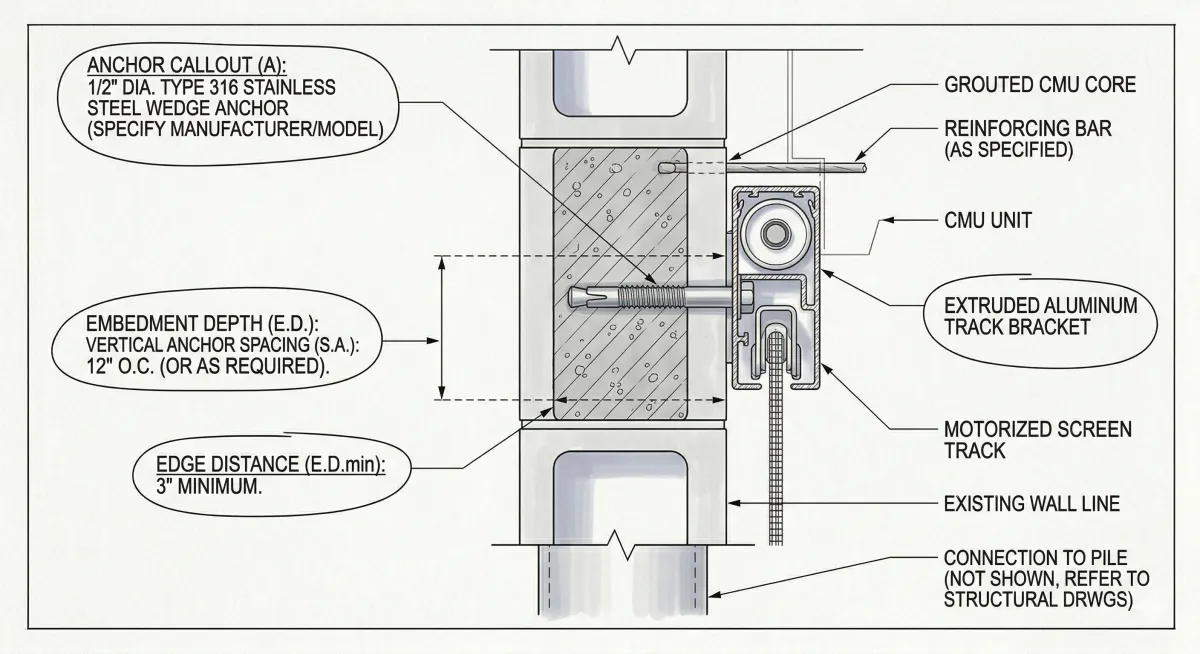
CMU substrates are the most common attachment condition for motorized screens in Florida and Gulf Coast construction. CMU walls introduce the most significant substrate variability because block cores may be solid, partially grouted, or hollow, and the block's net area and compressive strength vary by unit specification.
The product approval installation details for CMU attachments typically specify one of two conditions:
Condition 1: Grouted solid cores. The anchor is installed into a core that was grouted solid during construction. Grouted cores provide the highest anchor capacity because the anchor is bearing into a continuous concrete-like matrix rather than relying on the face shell of the hollow block. Anchor capacity in grouted CMU is evaluated per ACI 318-19 Chapter 17 (Anchoring to Concrete) using the Concrete Capacity Design (CCD) method, with the concrete compressive strength of the grout (f'c typically 2,000 to 3,000 psi for grouting applications) as the reference material.
Condition 2: Hollow cores with masonry anchor rated for hollow CMU. Where grouted cores are not available and the product approval permits hollow-core anchoring, masonry anchors evaluated under ICC-ES AC56 (Acceptance Criteria for Expansion Anchors in Masonry Elements) or published manufacturer data for hollow CMU must be used. Hollow CMU anchor capacities are substantially lower than grouted-core capacities because the anchor bears only against the block face shell, which has limited bearing area. Engineers must confirm that the hollow-core anchor's published allowable loads in the applicable block size and net area meet the calculated demand before specifying.
Edge distance requirements in CMU: Anchors installed too close to the edge of a CMU block or to a mortar joint have reduced capacity because the failure cone is truncated by the free edge. Most product approval installation details specify a minimum edge distance from the face of the block (typically 1.5 to 2.5 inches) and a minimum distance from the block's end or from mortar joints. Violating edge distance requirements is one of the most common field deficiencies in masonry anchor installations and cannot be corrected after the anchor is set without relocating the attachment point.
Poured Concrete Substrates
Anchor capacity in poured concrete is calculated per ACI 318-19 Chapter 17 using the CCD method. The three primary failure modes for tension (pullout) loading are: concrete breakout, anchor pullout, and concrete side-face blowout for large-diameter anchors near edges. For shear loading, the primary failure modes are steel failure and concrete pryout.
The concrete compressive strength (f'c) and the effective embedment depth (h_ef) are the primary variables governing concrete breakout capacity. Engineers must confirm f'c from the project structural drawings or from core test data for existing concrete; assuming a default f'c without verification is not acceptable in a structural calculation submitted for permit review.
For cast-in-place anchors (where the anchor is set before the concrete is poured), headed studs or J-bolts provide the highest capacity because they engage the full concrete breakout cone from depth. For post-installed anchors in existing concrete (the more common condition for motorized screen retrofits), the anchor type must be selected based on the published ICC-ES Evaluation Service Report (ESR) for the specific anchor in the applicable concrete condition.
Wood Frame Substrates
Wood frame substrates are the second most common condition in residential construction and the most susceptible to capacity variability based on lumber species, grade, moisture content, and framing member cross-section.
Attachment to Structural Framing Members
Motorized screen tracks and headers must attach to structural members with adequate cross-section to carry the applied loads: headers, jamb studs doubled to form the rough opening jack and king stud assembly, rim joists, or structural blocking members. Attachment to sheathing, siding, or non-structural framing elements (cripple studs, blocking between non-load-bearing studs) is not compliant with product approval installation requirements.
Screw and Lag Bolt Capacity in Wood
For screws and lag bolts used in wood frame attachment, allowable lateral (shear) and withdrawal (pullout) loads are calculated per the National Design Specification (NDS) for Wood Construction, published by the American Wood Council. NDS Table 11J provides reference lateral load design values for lag bolts in wood-to-wood connections. Reference values are adjusted by the NDS adjustment factors for load duration (CD), wet service conditions (CM), temperature (Ct), group action (Cg), and geometry (C_delta).
For coastal construction where moisture exposure is a regular condition, the CM adjustment factor for wet service conditions reduces allowable loads by 25 percent for connections that will be exposed to periodic wetting. Engineers specifying wood frame attachments for motorized screens in coastal or high-humidity environments must apply CM = 0.75 unless the framing is sealed and protected from moisture.
Minimum Framing Member Requirements
The product approval installation details specify minimum lumber dimensions for the framing member receiving the track or header anchors. A common specification is 2× nominal lumber (1.5-inch actual) for track attachments and 3× or 4× nominal lumber (or LVL header) for header attachments on spans exceeding 8 feet. The engineer must verify that the framing as built matches the specified minimum and that the cross-section is adequate for the applied loads, particularly in large-span applications where header moment demand may require larger section sizes than the minimum product approval specification assumes.
Specifying Structural Attachments for a Motorized Screen Project?
One Track provides engineers with product-specific anchor load data, tested attachment configurations, and stamped structural details for large-span and high-wind-zone installations. Access One Track's engineering documentation at onetrackscreens.com
Step 3: Steel and Aluminum Substrates
Commercial projects increasingly specify motorized screens attached to structural steel framing, aluminum curtain wall systems, or composite structural members. Each material category requires a distinct attachment approach.
Structural Steel Substrates
Attachment to structural steel members (wide-flange sections, HSS tubes, steel columns) uses through-bolting, welded stud attachments, or self-drilling screw connections depending on the steel member's section and the accessibility of the back face for through-bolting.
Through-bolt connections: The highest-capacity connection for steel attachment. The bolt bears in bearing on both the track mounting flange and the steel member flange or web. Bearing capacity is calculated per AISC 360-22 Section J3 (Bolts and Threaded Parts in Bearing Connections). Minimum bolt diameter for motorized screen attachments is typically 3/8 inch, with 1/2 inch preferred for high-wind-zone applications.
Self-drilling screw connections to steel: For connection to steel members with limited accessibility for through-bolting, self-drilling screws (tek screws) rated for metal-to-metal applications are used. Allowable shear loads for self-drilling screws in steel substrates are published in manufacturer data sheets and must be confirmed against the calculated per-fastener demand. Self-drilling screws in steel are susceptible to fastener pull-through failure under high tension loads; through-bolts are preferred for header attachments where tension loads from negative wind pressure are significant.
Corrosion compatibility: Steel substrates and aluminum track components create a galvanic pair. When aluminum motorized screen components are attached directly to structural steel, the contact surface must be isolated with neoprene tape, neoprene-coated washers, or a painted barrier to prevent galvanic corrosion. This is not a secondary maintenance consideration; it is a structural design requirement. Galvanic corrosion at untreated aluminum-steel contact points in coastal environments can reduce section capacity measurably within 3 to 5 years of installation.
Aluminum Curtain Wall and Storefront Systems
Motorized screens attached to aluminum curtain wall or storefront framing require coordination with the glazing contractor to confirm that the curtain wall mullion sections have adequate capacity to carry the transferred screen loads into the building structure without exceeding the mullion's published load capacity or introducing loads that were not accounted for in the curtain wall's original structural design.
The engineer specifying the screen attachment must obtain the curtain wall manufacturer's mullion section properties and allowable load tables, confirm the mullion's connection to the building structure (floor slab anchor or steel embed), and verify that the additional screen loads do not exceed the mullion system's design capacity. Where the additional load from the screen exceeds available mullion capacity, the engineer must either specify a supplemental steel mounting frame behind the curtain wall face (introducing the screen loads directly into the building structure rather than through the mullion) or coordinate a curtain wall redesign with the glazing contractor.
Step 4: Edge Distance, Spacing, and Group Effects
Anchor capacity calculations that treat each anchor as independent are correct only when anchors are spaced sufficiently far apart that their individual failure cones do not overlap. When anchors are spaced closely enough that their failure cones interact, the group capacity is less than the sum of the individual capacities, and the group effect must be accounted for in the calculation.
Edge Distance Requirements
Edge distance (c_a) is the distance from the center of an anchor to the nearest free edge of the substrate. Free edges include: the end of a CMU block, the edge of a concrete slab or foundation, the edge of a structural framing member, and the edge of any substrate discontinuity that would truncate the anchor's failure cone.
The minimum edge distance requirements for post-installed anchors in concrete and masonry are published in the anchor manufacturer's ICC-ES ESR report. Typical minimum values for expansion anchors in normal-weight concrete range from 4 to 8 anchor diameters measured from the anchor centerline. Failure to maintain minimum edge distances is the second most common anchor installation deficiency after grouted-core omission in masonry.
Anchor Spacing and the Group Capacity Calculation
When multiple anchors are installed in a group, the critical edge distance and critical spacing that govern the group breakout capacity are:
For concrete (ACI 318-19 Chapter 17):
Critical edge distance: c_ac = maximum of 1.5h_ef or the anchor's critical edge distance per the ESR report
Critical anchor spacing: s_cr = 3h_ef for concrete breakout in tension
When anchor spacing s is less than s_cr, the group breakout capacity (N_cbg) is calculated using the projected failure area for the group rather than the sum of individual failure areas.
For a linear array of anchors along a cassette header, the group capacity is:
N_cbg = (A_Nc / A_Nco) × Ψ_ec,N × Ψ_ed,N × Ψ_c,N × Ψ_cp,N × N_b
Where A_Nc is the projected failure area of the anchor group, A_Nco is the reference projected area for a single anchor, and the Ψ factors are modification factors for eccentricity, edge distance, cracking, and post-installed anchor conditions per ACI 318-19 Table 17.6.2.1.
For most motorized screen header anchor configurations with anchors at 12-inch spacing and embedment depths of 2 to 3 inches, the anchors will be within the critical spacing (3h_ef = 6 to 9 inches for typical embedment depths), requiring the group capacity calculation rather than independent anchor capacity summation.
This is the most common omission in field anchor calculations. Engineers who sum individual anchor capacities without checking whether group effects apply will overestimate the system's actual capacity, potentially by 20 to 40 percent for closely spaced anchors at shallow embedment depths.
Step 5: Corrosion Protection and Coastal Environment Requirements
Structural attachment hardware for motorized screens installed in coastal environments is subject to accelerated corrosion from salt air, humidity cycling, and UV exposure. The specified anchor material must be appropriate for the long-term exposure environment.
Anchor Material Classification for Coastal Applications
Zinc-plated carbon steel anchors: Standard hardware store product. Adequate for interior or protected applications. Not appropriate for exterior coastal installations; zinc coating in salt air environments shows measurable corrosion within 1 to 2 years. Not compliant for use in exposed exterior motorized screen applications.
Hot-dip galvanized anchors (ASTM A153): Zinc coating weight of 1.85 oz/ft² minimum. Suitable for moderate exterior exposure but not for applications within 1,000 feet of saltwater where continuous salt spray exposure occurs. Galvanized coating in direct salt spray environments has a service life of 5 to 10 years before the base steel becomes exposed.
Type 304 stainless steel: Suitable for most coastal exterior applications. Not appropriate for chloride-rich environments (within 300 feet of surf zone or marine industrial environments) where pitting corrosion of 304 stainless can occur.
Type 316 stainless steel: The correct specification for anchors in direct coastal exposure within 1,000 feet of saltwater, and mandatory for any installation within 300 feet of the surf zone or in marine environments. Type 316 stainless provides superior chloride resistance compared to Type 304 through the addition of molybdenum (2 to 3 percent) to the alloy chemistry. ASTM A276/A276M is the applicable material standard.
Dissimilar Metal Contact: Galvanic Corrosion Mitigation
The aluminum track components of a motorized screen system are anodic relative to steel fasteners and masonry-embedded steel anchor bodies. In the presence of moisture, the aluminum corrodes preferentially at the contact interface. For coastal applications:
All contact between aluminum track components and steel anchors must be isolated with neoprene or EPDM gaskets, tape, or coatings
Stainless steel anchors in contact with aluminum do not create a problematic galvanic pair because their galvanic potential difference is minimal (both are passive metals in most environments)
Zinc-plated anchors in contact with aluminum accelerate zinc corrosion; this combination is not appropriate for exterior applications regardless of coastal proximity
Producing the Stamped Structural Attachment Calculation
For large-span commercial installations, high-wind-zone residential projects, HVHZ applications, or any project where the building official requires a stamped attachment calculation, the engineer must produce a formal calculation package that documents the following:
Calculation cover sheet:
Project name, address, date
Engineer of record name, license number, and signature
Applicable codes and standards (ASCE 7-22, ACI 318-19, NDS 2018, IBC 2021, Florida Building Code 2023 as applicable)
Product approval or NOA number and version date for the screen system being attached
Applied load calculation:
Basic wind speed (V) and source (ASCE 7-22 wind speed maps or ATC Hazards Tool)
Exposure category and basis for classification
Design wind pressure (p) calculation for the applicable building height, zone classification, and effective wind area
Total applied force (F_total) and load distribution to header and track attachments
Per-anchor applied load (F_per_anchor) for the specified anchor count and spacing
Anchor capacity calculation:
Anchor manufacturer, model, diameter, and embedment depth
ICC-ES ESR number and version date for the anchor
Published allowable tension and shear capacities for the substrate type and anchor configuration
Group capacity calculation if anchor spacing is less than 3h_ef in concrete or CMU
Edge distance verification against minimum requirements
Demand-to-capacity ratio (applied load / allowable capacity ≤ 1.0 for LRFD; applied load × safety factor ≤ allowable capacity for ASD)
Substrate verification:
Substrate type confirmed from project documents or field investigation
Concrete compressive strength (f'c) for concrete calculations
CMU unit specification and grout specification if grouted cores are required
Lumber species and grade for wood frame calculations with wet service adjustment factor applied if applicable
Steel member designation and section properties for steel attachment calculations
For HVHZ projects in Miami-Dade and Broward Counties, the stamped attachment calculation must demonstrate compliance with the NOA installation details. If the site-specific conditions require an attachment configuration that differs from the NOA installation details, a Miami-Dade Product Control Division variance request is required before the modified attachment can be used. Builders specifying HVHZ-compliant hurricane screen systems should coordinate with Max Force Hurricane Screens for NOA-specific attachment engineering documentation.
The Next Gen Screens blog series provides complementary engineering references across the series, including wind load calculation methodology (Blog 1), motor torque and load requirements (Blog 4), commercial large-span structural coordination (Blog 6), and the installation sequence for structural rough-in verification (Blog 9).
Conclusion: Structural Attachment Engineering Begins with Load Calculation, Not Anchor Selection
The anchor schedule in a product approval installation detail is a tested minimum for the certified conditions, not a universal answer for every site condition. Engineers who treat the product approval anchor schedule as the end of the structural attachment question will produce calculations that are technically compliant for standard conditions but structurally inadequate for large-span, high-wind-zone, or non-standard substrate applications.
The engineering discipline for motorized screen structural attachment is not substantially different from any other anchored component specification: calculate the load, select an anchor with published capacity data referenced to a recognized standard, verify edge distance and spacing requirements with group effects where applicable, specify the correct material for the exposure environment, and document the calculation. Applied systematically across every project where the site conditions exceed the standard product approval conditions, this process produces attachment specifications that perform through the full service life of the system under the design loads the building was designed to resist.
Need product-specific anchor load data, ESR references, or stamped attachment calculation support for your current project? The engineering resource library at Next Gen Screens provides technical documentation for the professional's workflow. Access the full library at nextgenscreens.com.